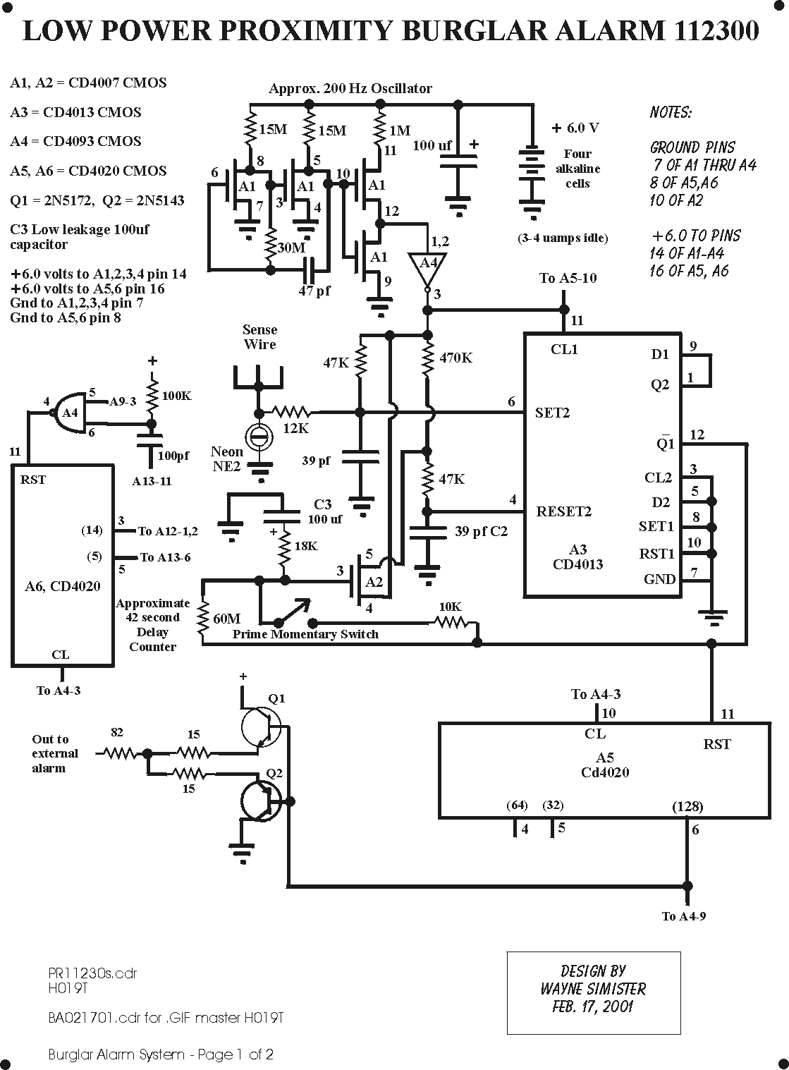
This is a complete burglar alarm system which includes a sensitive proximity detector, coded push button turn-on and turn-off, and reliable, very low power battery operation. Batteries should last up to four years when "C" or "D" cells are utilized.
The proximity detector is similar to that described in other schematics on this home page.... a zig-zagged sensing wire running beneath a wooden floor or under the rug senses a body above. The unit should have an earth ground for best results. This sensing wire senses a change in capacitance.
A remote turn-on, turn-off push button switch controls the circuit operation. Two pushes of this switch turns the circuit on. Four pushes turns it off. Once the system is activated, approximately 40 seconds are allowed before the circuit arms.
Upon a body detection, the alarm sounds for 40 seconds.... a fast beeping from the Sonalert alarm. The alarm can be triggered up to four times. After the fourth trigger, the alarm shuts off and no further alarms will sound until the circuit is turned back off then on again. This prevents a condition where, if for some reason, accidental triggers will not continue to sound the alarm indefinitely.
A PRIME push button is installed on this alarm to allow a quick charge of C1 (100 uf capacitor) to operating voltage. The only time this button has to be used is after a new battery installation. Holding the switch down for several seconds will charge C1 to the operating voltage. Should a regular beeping be heard, again momentarily touch the PRIME push button until it ceases.
Since the proximity detection circuit is active regardless of whether the circuit is armed or not, a special output, "Out to External Alarm," is available. This sends a high current +5.5 volt pulse out each time a body is detected by the circuit. Such an output may be useful for the trigger of remote alarm systems.
A1 is a 200 Hz oscillator which outputs through a Schmidt Trigger, A4-12,3 to sharpen the rise and fall edges.
A3 is the capacitance detector (described more elaborately in other sections of this home page). A3-12 outputs a square-wave correction voltage which in turn charges or discharges C1 to keep the circuit "in balance." This way, it is self-adjusting to different environments for the sensing wire. A2-3,4,5 acts as the variable resistor to adjust the time constant to achieve balance.
When a body is detected, Q1-12 stops outputing a square wave because of circuit inbalance. A5 is a counter which looks for at least 128 missing counts before outputing a "detect" signal. This prevents natural circuit noise from triggering the alarm.
Q1 and Q2 output a short pulse each time a trigger is detected at A5-6. This output is there regardless of whether the alarm circuit has been turned on or off and can be used for external alarm triggering.
(Page 2 of schematic)
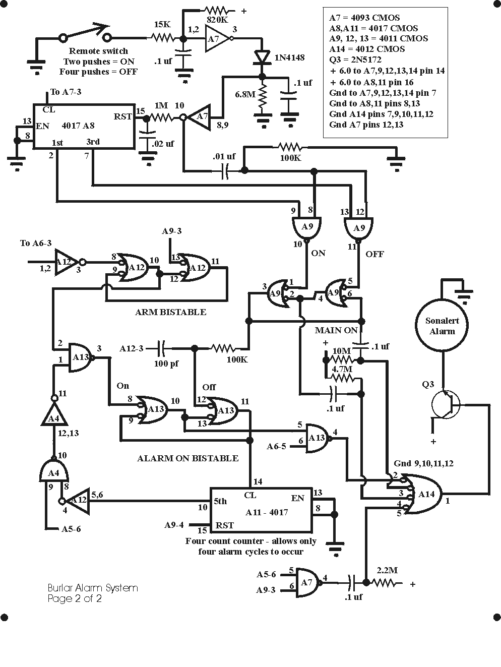
The REMOTE SWITCH can be mounted for convenient turn-on and turn-off of the circuit. Two pushes turn the alarm on. Four pushes turn it off. Coding may be changed by using different output pins on A8 (4017).
The alarm is not armed until the ARM BISTABLE is turned on. This occurs approximately 40 seconds after turn-on. A full count of A6-3 sends a high pulse out which in turn arms the alarm circuit.
Once armed, a detection pulse from A5-6 is "anded" with the ARM BISTABLE at A13-1,2,3. This, in turn, activates the ALARM ON BISTABLE. (A full count of A6-3 determines alarm on time)
When the ALARM ON BISTABLE has gone off four times, the counter, A11-10, shuts the circuit down preventing any further triggers from the proximity detection section.
A14-1,2,3,4,5 "ands" functions for the Sonalert alarm. When the circuit is turned on, a short 1/2 second beep is heard. When the circuit is turned off, a one second beep is heard. Any time a body is detected, a short 1/4 second beep is heard providing the circuit is on but not yet armed. Also, this short 1/4 second beep is heard after the ALARM BISTABLE has fired more than four times -- a reminder that the circuit has not be reset by a turn-off and turn back on.
Since this circuit draws only 3 to 4 microamps during idle, battery life is extremely long. The only time appreciable power is drawn from the batteries is during the Sonalert on times. Too, since only a few electrolytic capacitors are utilized, reliability is quite good. It's an install and forget circuit.
There are TWO pages of schematic for this circuit. RIGHT-clicking on the image will let you download a clearer large, printable image.


Page Modified March 22, 2001