Right click on image to save printable .GIF image to file
Similar proximity detector schematic only with delay on feature (Nov. 3, 2000)
Page Modified February 20, 2009
This project was generated in search for a simple, small, battery operated device which would allow installation under a wooden floor as part of a simple alert system or even as a burglar alarm.
A low frequency oscillator and use of CMOS circuitry are responsible for its low power consumption resulting in excellent battery life from 3 - AA cells.
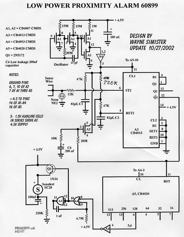
The low frequency oscillator is designed using the CD4007, A1. The pulse is shaped and sharpened by A4, pins 1,2, and 3.
The circuit around A3, CD4013 - a "D" flip flop, is actually a very sensitive capacitance change detector. It is automatically kept in balance. Any imbalance due to someone nearing the sensing wire will be detected.
How it works:
One section of the CD4013, "D" flip flop normally has a balanced input going to the direct set and direct reset inputs (ST2 and RST2). C1 and C2 are discharged by the common negative low of the clock signal from A4-3. Depending upon which input (ST2 or RST2) "releases" control of the flip flop last -- determines the state Q2 will take. The state of Q2 is latched in during the positive going rise of the A4-3 oscillator clock signal. This is output as a feedback signal at NOT Q1.
In actuality, the signal at NOT Q1 is constantly alternating between high and low to give proper feedback signal to the servo loop filter formed by the 20 megohm resistor, the 10K resistor, and C5 (200 ufd. low leakage electrolytic capacitors). This servo loop is completed by means of A2 pins 3,4, and 5 which constantly adjusts the resistance leg of C2, keeping a match to the time constant -- that of the sensing wire, 47K resistor, and C1.
A5 (CD4020) is a 14-stage counter. A5 is constantly being reset if the circuit is in balance. Should, however, an object approach the sensing wire, A5 starts counting. When a given count is reached, the monostable formed by A4, pins 8,9,10,11,12 and 13 is fired and a short alarm "ding" is given by the piezoelectric Sonalert device. By adjusting which output you tap off on A5 (pins 4,5,6,7,12 and 13) determines the stability and sensitivity from normal background noise and capacitance changes.
The circuit requires very little power due to the design. Battery life should easily exceed two years using alkaline batteries.
IMPORTANT NOTE: This ciruit requires several hours "to settle" after batteries are installed. Proper operation doesn't occur until the 200 uf., C6, capacitor reaches a stabilized charge of approximately half the supply voltage.
Right click on image to save printable .GIF image to file
Similar proximity detector schematic only with delay on feature (Nov. 3, 2000) Page Modified February 20, 2009