Right click on the schematic to save a printable image to disk.
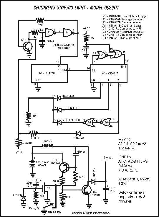
A voltage step-up circuit consisting of Q2, Q3, and Q4 outputs about 7 volts. The 2N7000 (Q2) acts as an on-time delay for this 7-volt supply. When the pushbutton is depressed, the circuit cycles on because of the sudden rising positive voltage at the gate of Q2. On-time is determined by the time it takes the 15 megohm resistor to charge the 22uf capacitor and reach the pinch-off voltage of Q2.
A 2200 Hz oscillator is formed by Q1, A1-1,2,3,4,5,6. Q1 acts as a discharge for the .001 uf capacitor. The frequency of this oscillator is determined by the time constant formed with the .001 capacitor and R2 (470K) during the red and green LED on cycles, or the parallel resistance of R1 (330K) and R2 when the yellow LED is on. Thus, the yellow cycle is made shorter.
A2 (CD4020)is a 14-stage counter used to divide down the oscillator frequency. Pin 3 of A2 puts out a positive-going pulse approximately every six-seconds during the Red and Green LED phases, and every 3 seconds during the yellow phase. This lets the red and green LEDs stay on for about six seconds -- the yellow for about three seconds.
A3 (CD4017) outputs sequential signals on pins 3, 2, and 4 which, in turn, light the LEDs in proper sequence.
A1-8,9,10,11,12,13 acts to reset the decade counter, A3 (CD4017), after each series of three counts. A 10M and .01 capacitor at A1-13 assures the circuit to come up lighting the Red LED when the circuit is first turned on.