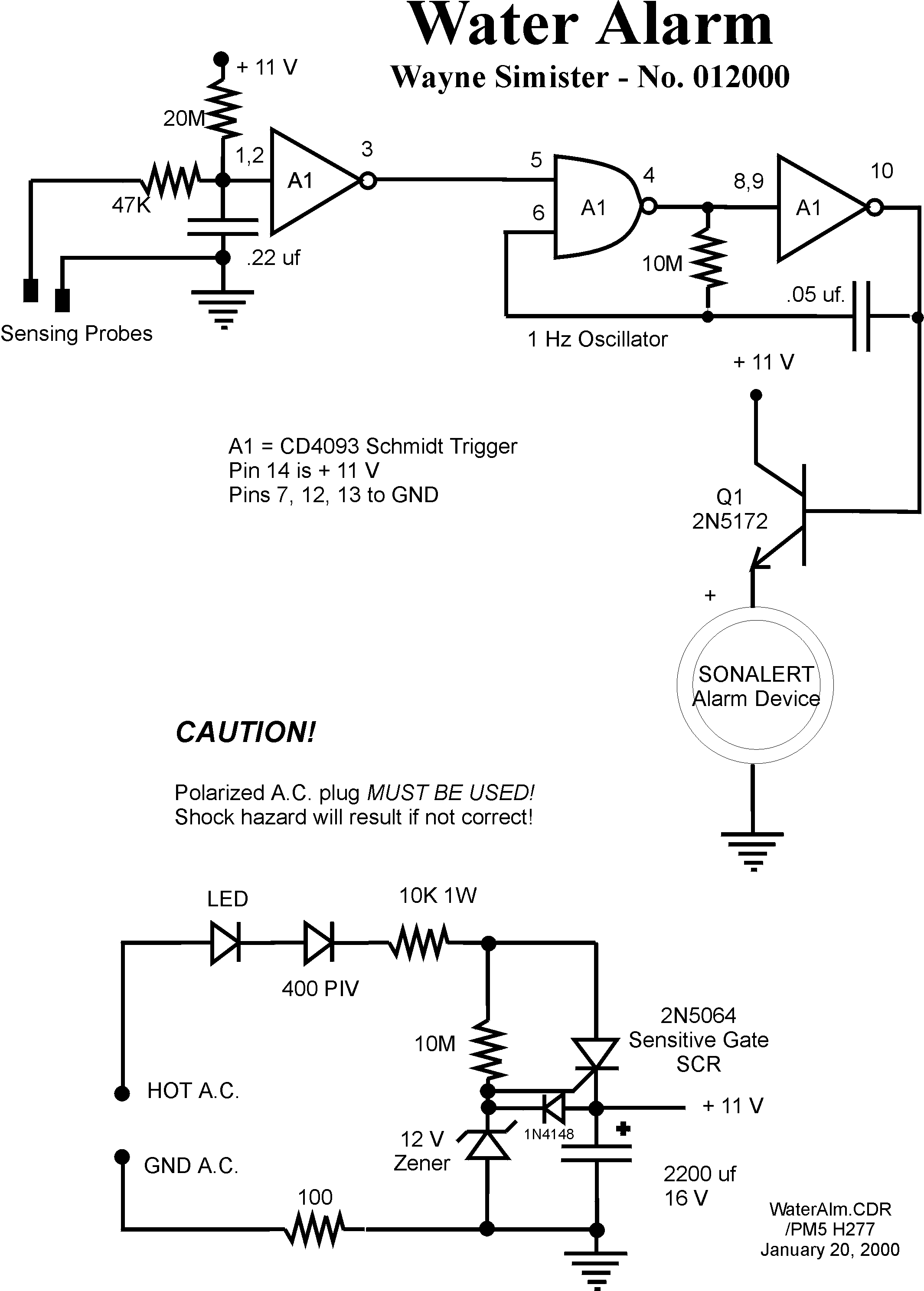
Schematic Diagram
A1 (CD4093) is an integrated circuit with four independent 2-input NAND gates. One gate is not used.
A1, pins 1,2 and 3 form a simple high impedance input amplifier. A 20-megohm resistor charges the .22 uf capacitor to +11 volts. If, however, the sensing probe is immersed in water, the .22 uf capacitor is discharged through the 47K resistor. This "low" is amplified and inverted. Pin 3, therefore, now has a high, 11 volts, going into pin 5 of the second CD4093 amplifier which is wired as a NAND gate. Once pin 5 goes high, an oscillator is formed by the combination of A1 pins 5,6,7 and A1 pins 8,9, and 10. This oscillates at approximately 1 Hz. This 1 Hz signal is further amplified by NPN transistor, Q1.
Thus, when water is detected, the Sonalert Alarm Device beeps about once every second.
The power supply uses a sensitive gate SCR. The SCR is triggered when the voltage on the 2200 uf. electrolytic falls below approximately 11 V. A 12-volt Zener diode determines the voltage on the 2200 uf. capacitor.
The .22 uf. capacitor at pins 1,2 of A1 allows a long line to the sensor probes.... It filters out any AC or high frequency disturbance.
The 1N4148 diode protects accidental overcharging of the 2200 uf. capacitor should some electrical line interference cause the sensitive gate SCR to trigger erratically.
The circuit draws very little power in the "wait" mode. About 5 milliamps are drawn when the alarm sounds.

Page Modified January 21, 2000